

Measure any AC voltage (250VAC) with ZMPT101B and ESP8266 12E with Android App / Adafruit IO MQTT
Need to use this with Arduino? Check that: Easy measure of AC Voltage using Arduino and ZMPT101B
Please be very careful when you mess with the powerline !
Hello, everyone and welcome to SurtrTech channel, this is a project about how to measure any AC voltage (up to 250 VAC 50/60 Hz) using the ZMPT101B module, and by any I’m talking about the signal shape, because measuring a sinewave signal is quite simple but when it comes to some strange shapes like a TRIAC’s one you need a special module and code like you gonna see here.

This is an example of the signal shape when you use a Triac, here I will use a Triac based light dimmer, and in my previous tutorial when I used Arduino I showed that the code I’ve made performed much better than a cheap multimeter or a non TRMS multimeters.

This is the module I’m using, it’s called ZMPT101B, but actually this is name of the transformer (big blue thing), it has a LM358 Amplifier.

Depending on which board you’re using the output voltage will be different and also the offset, for Arduino the extremums were 0 and 5V with a 2.5V offset.
For the ESP8266 the extremums are 0 and 3.3V with a 1.65V offset.
This is why the module is good, it takes a signal that will burn your board and adapt it without losing its shape which is very important for a TrueRMS measuring.
About the power !
When I tested this module with the Arduino board, it was very stable because I was using 5V, but when I wired it with the ESP8266 12E, I noticed some voltage drop, that’s why I used a Li battery and a converter to keep the power stable (3.3 VDC).

I don’t know, maybe because I have an old board (2017), ESP8266 12E (NodeMcu V1.0), or the board is not drawing enough power from the USB cable…. but if it works for you it’s pretty much the same thing for these kind of boards, even the 5V ones.
First calibration
Here we want to calibrate our module first, using the built-in potentiometer, to adjust the signal amplification.

Like I explained before, theoretically, the 250 VAC (RMS) signal should be reproduced as a signal that goes from 0 to 3.3V and centered around 1.65V, which means we can exploit all the ADC range which is 0 – 1023, and it will be more precise to calculate the values.
But unfortunately we cannot do that, as the signal can be lost at some points, so we have to reduce the amplification and instead of exploiting all 0 – 3.3V we’ll have to work with a smaller range, and that’s why using 5V boards is better.
Wiring

Here in the wiring I have the module hooked up with the board, and I have also my test bench, I’ve chosen to measure the Voltage of an incandescent light bulb wired with a TRIAC based light dimmer, you can measure what you want.
All you have to do now is put the MAXIMUM voltage (without surpassing 250VAC), in my case I have around 230V/50Hz, you can take it directly from the socket or after A full cycle light dimmer.
Code
Now you upload that code and open the Serial Plotter of the Arduino IDE.
|
1 2 3 4 5 6 7 8 |
void setup() { Serial.begin(115200); pinMode(A0,INPUT); } void loop() { Serial.println(analogRead(A0)); //delay(100); } |
Yes this the code that you’ll need for the moment, that delay you can keep it or remove it you’ll notice the difference once you test both (or check the video above).
Calibration
Once you open the Serial Plotter you gonna see some shapes passing by.
This is what you don’t want: A shape that has an horizontal straight line on the extremums….

This is what you need to see: Some Sinewave like signal, so keep turning your potentiometer until you can see something like this, and pay attention here you are controlling the signal amplification, so you need to have the maximum values without disturbing the shapes.

Once this is done, and keep in mind that you shouldn’t keep turning it because it will affect all future calculations.
True RMS measuring and calibration
Here we gonna see the important code for measuring the TRMS value, but it should be calibrated first, and once you start measuring “correctly” the values you can do whatever you want with your values: Send them via MQTT, create a small App, use with Blynk….
First you should put 0 VAC as the module input, of course you can keep the same wiring.
Library
Download the Filters library here !
Code
Download the code here ! or check below.
This is the code that you can use first to get familiar with the library, measuring and calibration, it doesn’t have a third party or in need to be connected to the WIFI, all it does is measuring the TRMS values and display them on the Serial Monitor, and of course you can recalibrate as you need when you use other things.
Those are pretty much the three important parts of the calibration:

For the windowLength, with Arduino I used “40/testFrequency” it was nice but with the ESP8266, the “100/testFrequency” gave better results, you can try and see what suits you the most.
For the moment it’s better to keep the intercept and slope as they are, and as you can see they don’t change the “Sigma” which is what we calculate in this code.
![]()
|
1 2 3 4 5 6 7 8 9 10 11 12 13 14 15 16 17 18 19 20 21 22 23 24 25 26 27 28 29 30 31 32 33 34 35 36 37 38 39 40 41 42 43 44 45 46 47 48 49 50 51 52 53 54 55 56 57 58 59 60 61 62 63 64 65 66 67 68 69 70 71 72 73 |
/* This code works with ESP8266 12E or Arduino and ZMPT101B AC voltage sensor up to 250 VAC 50/60Hz * It permits the measure of True RMS value of any AC signal, not only sinewave * The code uses the Sigma "Standard deviation" method and displays the value every "printPeriod" * check http://www.SurtrTech.com for more details */ #include <Filters.h> //Library to use #define ZMPT101B A0 //Analog input float testFrequency = 50; // test signal frequency (Hz) float windowLength = 100/testFrequency; // how long to average the signal, for statistist, changing this can have drastic effect // Test as you need int RawValue = 0; float Volts_TRMS; // estimated actual voltage in Volts float intercept = 0; // to be adjusted based on calibration testin float slope = 1; /* How to get the intercept and slope? First keep them like above, intercept=0 and slope=1, * also below keep displaying Calibrated and non calibrated values to help you in this process. * Put the AC input as 0 Volts, upload the code and check the serial monitor, normally you should have 0 * if you see another value and it is stable then the intercept will be the opposite of that value * Example you upload first time and then you see a stable 1.65V so the intercept will be -1.65 * To set the slope now you need to put the voltage at something higher than 0, and measure that using your reference TRMS multimeter * upload the new code with the new intercept and check the value displayed as calibrated values * Slope = (Measured values by multimeter)/(Measured values by the code) * Place your new slope and reupload the code, if you have problems with calibration try to adjust them both * or add a new line to calibrate further * Slope and intercept have nothing to do with the TRMS calculation, it's just an adjustement of the line of solutions */ unsigned long printPeriod = 1000; //Measuring frequency, every 1s, can be changed unsigned long previousMillis = 0; RunningStatistics inputStats; //This class collects the value so we can apply some functions void setup() { Serial.begin(115200); // start the serial port Serial.println("Serial started"); inputStats.setWindowSecs( windowLength ); } void loop() { ReadVoltage(); //The only function I'm running, be careful when using with this kind of boards //Do not use very long delays, or endless loops inside the loop } float ReadVoltage(){ RawValue = analogRead(ZMPT101B); // read the analog in value: inputStats.input(RawValue); // log to Stats function if((unsigned long)(millis() - previousMillis) >= printPeriod) { //We calculate and display every 1s previousMillis = millis(); // update time Volts_TRMS = inputStats.sigma()* slope + intercept; // Volts_TRMS = Volts_TRMS*0.979; //Further calibration if needed Serial.print("Non Calibrated: "); Serial.print("\t"); Serial.print(inputStats.sigma()); Serial.print("\t"); Serial.print("Calibrated: "); Serial.print("\t"); Serial.println(Volts_TRMS); } } |
Result
Once you upload the code open the serial monitor, do not forget 0VAC as the input. You’ll see something like this:

There are some fluctuations, it’s not that big, normally if I had a stable value there like 1.88, the intercept will be then -1.88, so what you need to see there is 0 or close to 0. In my case I kept the intercept as 0.
Now put the intercept value as you found better and reupload the code to the board.
Also put the AC input at some value, for example your network RMS, measure it using the multimeter to get the right value, and open again the serial monitor.

Those are the values I got it was around “90.5” in calibrated. (They are the same because the intercept is 0).
Measured with the multimeter “228.6”.
So the Slope will be = 228.6/90.5
Apply the new slope to the code, you can discard the “non calibrated value”.
This is pretty much the difficult and most important task to achieve, once you get this you can add some WiFi or Internet functions as you want, I’ve chosen some few to put here as example.
Using with Adafruit IO MQTT
Now that you are able to measure the AC voltage you can send those values to a third party, here I took the Adafruit IO MQTT as example.
“”There’s no detailed tutorial for this at the moment, let me know if needed””

Once you sign-in there, you should go to Feeds and Create a new feed (Pay attention it’s not unlimited). I’ve created a feed and named it “Test”.
Remember the name it’s important !
Then you go to Dashboards, create one and add a new block, here I added a Gauge.

Every Gauge need a feed so you chose the one you’ve created before.

And you adjust the settings as you need.

Now you’re ready to go all you need are some libraries and a suitable code.
Libraries
It’s better to go to the Arduino IDE Library Manager, and search for these ones below, if it asks you to download some other libraries because they are essentials, let it install them.

Code
Download the code here ! or check below.
In the code don’t forget to modify these things:
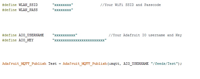
the “Test” is jut my Feed name !! You should replace both by your feed name. Of course then you’ll have your own slope and intercept as we said before.
|
1 2 3 4 5 6 7 8 9 10 11 12 13 14 15 16 17 18 19 20 21 22 23 24 25 26 27 28 29 30 31 32 33 34 35 36 37 38 39 40 41 42 43 44 45 46 47 48 49 50 51 52 53 54 55 56 57 58 59 60 61 62 63 64 65 66 67 68 69 70 71 72 73 74 75 76 77 78 79 80 81 82 83 84 85 86 87 88 89 90 91 92 93 94 95 96 97 98 99 100 101 102 103 104 105 106 107 108 109 110 111 112 113 114 115 116 117 118 119 120 |
/* This code works with ESP8266 12E and ZMPT101B AC voltage sensor * It can measure the TRMS of Any voltage up to 250 VAC 50/60Hz and send the values to Adafruit MQTT * Refer to http://www.SurtrTech.com for more details */ #include <ESP8266WiFi.h> //Libraries needed #include <Adafruit_MQTT.h> #include <Adafruit_MQTT_Client.h> #include <Filters.h> #define WLAN_SSID "xxxxxxxx" //Your WiFi SSID and Passcode #define WLAN_PASS "xxxxxxxx" #define AIO_SERVER "io.adafruit.com" #define AIO_SERVERPORT 1883 #define AIO_USERNAME "xxxxxxxxxx" //Your Adafruit IO username and Key #define AIO_KEY "xxxxxxxxxxxxxxxxxxxxxxxx" #define ZMPT101B A0 //ZMPT101B analog pin int Current_Time=0, Previous_Time=0, Period=10000; //We send a value every 10s, the maximum is 30 value per minute float testFrequency = 50; // test signal frequency (Hz) float windowLength = 100/testFrequency; // how long to average the signal, for statistist int RawValue = 0; float intercept = 0; // to be adjusted based on calibration testing float slope = 1; // to be adjusted based on calibration testing float Volts_TRMS; // estimated actual voltage in Volts //For more details about the intercept and slope check the Base code at SurtrTech WiFiClient client; Adafruit_MQTT_Client mqtt(&client, AIO_SERVER, AIO_SERVERPORT, AIO_USERNAME, AIO_KEY); Adafruit_MQTT_Publish Test = Adafruit_MQTT_Publish(&mqtt, AIO_USERNAME "/feeds/Test"); //My feed name is "Test" so pay attention to yours, remplace it at the name and "/feeds/Test" RunningStatistics inputStats; void setup() { Serial.begin(115200); delay(10); inputStats.setWindowSecs( windowLength ); Serial.println(); Serial.print("Connecting to "); Serial.println(WLAN_SSID); WiFi.begin(WLAN_SSID, WLAN_PASS); while (WiFi.status() != WL_CONNECTED) { delay(500); Serial.print("."); } Serial.println(); Serial.println("WiFi connected"); Serial.println("IP address: "); Serial.println(WiFi.localIP()); } void loop() { Volts_TRMS=ReadVoltage(); //We read the voltage, normally the function returns the Volts_TRMS value,you can do it directly in the Test.publish //But this is the syntax that worked for me, return a value to it self :D MQTT_connect(); //Keep the MQTT connected Current_Time=millis(); if(Current_Time - Previous_Time >= Period){ //Every period we send the value to the service provider Serial.print(F("\nSending Value ")); //The value is shown on the Serial monitor as well Serial.print(Volts_TRMS); Serial.print("..."); if (! Test.publish(Volts_TRMS)) { Serial.println(F("Failed")); } else { Serial.println(F("OK!")); } Previous_Time = Current_Time; } } void MQTT_connect() { //Auto reconnect to MQTT, otherwise it will trigger a watchdog reset int8_t ret; // Stop if already connected. if (mqtt.connected()) { return; } Serial.print("Connecting to MQTT... "); uint8_t retries = 3; while ((ret = mqtt.connect()) != 0) { // connect will return 0 for connected Serial.println(mqtt.connectErrorString(ret)); Serial.println("Retrying MQTT connection in 5 seconds..."); mqtt.disconnect(); delay(5000); // wait 5 seconds retries--; if (retries == 0) { // basically die and wait for WDT to reset me while (1); } } Serial.println("MQTT Connected!"); } float ReadVoltage(){ RawValue = analogRead(ZMPT101B); // read the analog in value: inputStats.input(RawValue); // log to Stats function Volts_TRMS = inputStats.sigma()* slope + intercept; // Volts_TRMS = Volts_TRMS*0.979; return Volts_TRMS; } |
Result
This is an example of the result, of course those values can be stored for some time, depending on you account settings, you can add some warnings if you want.

Using with local Android App
No tutorial about how to make this app with details is available, let me know if you need any.
In this section I’ve add a small App for Android that I made using MIT App Inventor 2.

This is how the app looks like, it’s a beginner thing to make you start, once you connect your ESP8266 to the Wifi it will have a local IP address, you can see it in the Serial monitor when the ESP8266 starts.
When you set your IP address press Connect, this will set which address to use for communication, and stores it in a database to be used later when you restart you app.
To get the Value press “Get Value”.
I kept in the code in case you want to send it as html format, just uncomment the lines.
Here you can download the app “.apk” so you can install it and use it.
Code
Download the code here, or check below. The code is very simple, it just sends the data whenever a client tries to connect to it, to use with multiple sensors it should be more elaborated.
|
1 2 3 4 5 6 7 8 9 10 11 12 13 14 15 16 17 18 19 20 21 22 23 24 25 26 27 28 29 30 31 32 33 34 35 36 37 38 39 40 41 42 43 44 45 46 47 48 49 50 51 52 53 54 55 56 57 58 59 60 61 62 63 64 65 66 67 68 69 70 71 72 73 74 75 76 77 78 79 80 81 82 83 84 85 86 87 88 89 90 91 92 93 94 |
/* This code works with ESP8266 12E and ZMPT101B AC voltage sensor * It can measure the TRMS of Any voltage up to 250 VAC 50/60Hz and send the values to Android App * The ESP8266 starts a local server and sends data whenever something is connected to it * Refer to http://www.SurtrTech.com for more details */ #include <ESP8266WiFi.h> #include <Filters.h> #define ZMPT101B A0 #define WLAN_SSID "xxxxxxxxxxx" //Your WiFI SSID and Passcode #define WLAN_PASS "xxxxxxxxxxx" float testFrequency = 50; // test signal frequency (Hz) float windowLength = 100/testFrequency; // how long to average the signal, for statistist int RawValue = 0; float intercept = 0; // to be adjusted based on calibration testing float slope = 1; // to be adjusted based on calibration testing float Volts_TRMS; // estimated actual voltage in Volts //Check the Base Code for ZMPT101B on SurtrTech for more details about the intercept, slope and windowLength unsigned long printPeriod = 1000; unsigned long previousMillis = 0; RunningStatistics inputStats; WiFiServer server(80); void setup() { Serial.begin(115200); Serial.println("Serial started"); inputStats.setWindowSecs( windowLength ); WiFi.disconnect(); delay(3000); WiFi.begin(WLAN_SSID, WLAN_PASS); while ((!(WiFi.status() == WL_CONNECTED))){ delay(300); } Serial.println("Connected"); Serial.println((WiFi.localIP().toString())); //Display the local IP Address, this will be needed when trying to connect server.begin(); pinMode(LED_BUILTIN, OUTPUT); //I added some blinking of the internal LED, so I can know when the ESP is connected digitalWrite(LED_BUILTIN, LOW); //And also when someone tries to get the value (it helps debugging) delay(1000); digitalWrite(LED_BUILTIN, HIGH); } void loop() { ReadVoltage(); WiFiClient client = server.available(); if (client) { //IF someone is trying to connect Serial.println("New Client"); //Shows new client on the serial monitor to show that someone is connecting + blinking digitalWrite(LED_BUILTIN, LOW); delay(300); digitalWrite(LED_BUILTIN, HIGH); client.println("HTTP/1.1 200 OK"); client.println("Content-type: text/html"); client.println(""); // client.println("<!DOCTYPE HTML>"); //Uncomment these lines if you want to send as HTML, it depends on the app and what it will receive // client.println("<html>"); client.println(Volts_TRMS); // client.println("</html>"); client.println(); digitalWrite(LED_BUILTIN, LOW); //LED blinking to show that data is sent delay(300); digitalWrite(LED_BUILTIN, HIGH); delay(100); digitalWrite(LED_BUILTIN, LOW); delay(300); digitalWrite(LED_BUILTIN, HIGH); } } float ReadVoltage(){ //Measure and calibrate the values to be sent RawValue = analogRead(ZMPT101B); // read the analog in value: inputStats.input(RawValue); // log to Stats function Volts_TRMS = inputStats.sigma()* slope + intercept; return Volts_TRMS; } |
Result
Power OFF

Power On, light dimmer turned a little:

Push further
If you’re into Mobile App Development, you can of course create a more elaborate app, with warnings if you want, notifications and most important to be able to connect via internet not only locally like this one.
There are some few modifications to do for example using Adafruit IO or ThingSpeak… to be able to get the data via internet using only this simple App created in APP Inventor.
That’s all folks !
Categories
Yassine View All
Automation and Electrical Engineer, Electronics amateur trying to share my little projects.
Thanks for another great tutorial. I am trying to get the ZMPT101B to work with ESP32 Wrover, but the filters library cannot compile and gives an error. Do you know of any alternative to filters.h for ESP32?
Thanks for another great tutorial. I am trying to get the ZMPT101B to work with ESP32 Wrover, but the filters library cannot compile and gives an error. Do you know of any alternative to filters.h for ESP32?
I really don’t know, never tested with ESP32.
Worked well with ESP8266 12E and Arduino UNO though.
I found the solution. There is a library called “ESP32 AnalogWrite” that needs to be included for the filters to compile. It can be found here: https://www.arduinolibraries.info/libraries/esp32-analog-write
Solution found. There is a library called “ESP32 AnalogWrite” which needs to be included to make the compiler happy. Can be found here: https://www.arduinolibraries.info/libraries/esp32-analog-write
compare101, this was good to hear that there was a way to compile, but sadly it still fails with the analogWrite part. did you get this to work? could you post the code?
Download the AnalogWrite library and include it at the top of ‘FilterTwoPole.cpp’ (ie: #include “analogWrite.h”). That worked for me. Will try to push an example to a public repo and let you know.
This work for me. Thank you sir
Got it all working, thanks for giving the input.
Glad I could help! Sidenote: ESP32 ADC is not the best out there. Many issues. Best way to approach them is using the ESP-IDF “adc.h” driver, otherwise you will be pulling your hair out. (I have a love-hate relationship with the ESP32 WROVER)
Sir, I am working on ESP32WROOM-32.And use ZMPT101B sensor to measure voltage.I used 3.3V adapter to ON ZMPT sensor but at the output side I found the waveform with too much ripple.I used RC filter but its not working. Can you please help me
How can I make a road lighting lamp 30W that can increase and decrease the intensity of lighting (dimming) by arduino
Hi, really appreciate the guide. I am able to get the readings perfectly dialed in with out the wifi. Once i load the mqtt version for every 5 messages it gets disconnected and reconnects to the mqtt server. i tried online servers local servers, diffrent boards(WEMOSd1, multiple nodemcu boards with the 12e chips) still no luck. Any suggestions?
Hi,
Thank you for sharing this guide. but how can i convert the calculation loop() into a function?